

Pressure Reducing Valves serve as core auxiliary components within fire water supply systems and automatic sprinkler systems. They find extensive application in stabilizing pressure, reducing pressure, and ensuring the safety of water supply networks.
Drawing upon relevant regulatory standards, this comprehensive guide systematically elucidates the working principles, installation and configuration criteria, key commissioning procedures, and routine maintenance requirements associated with pressure reducing valves.
Working Principles of Pressure Reducing Valves
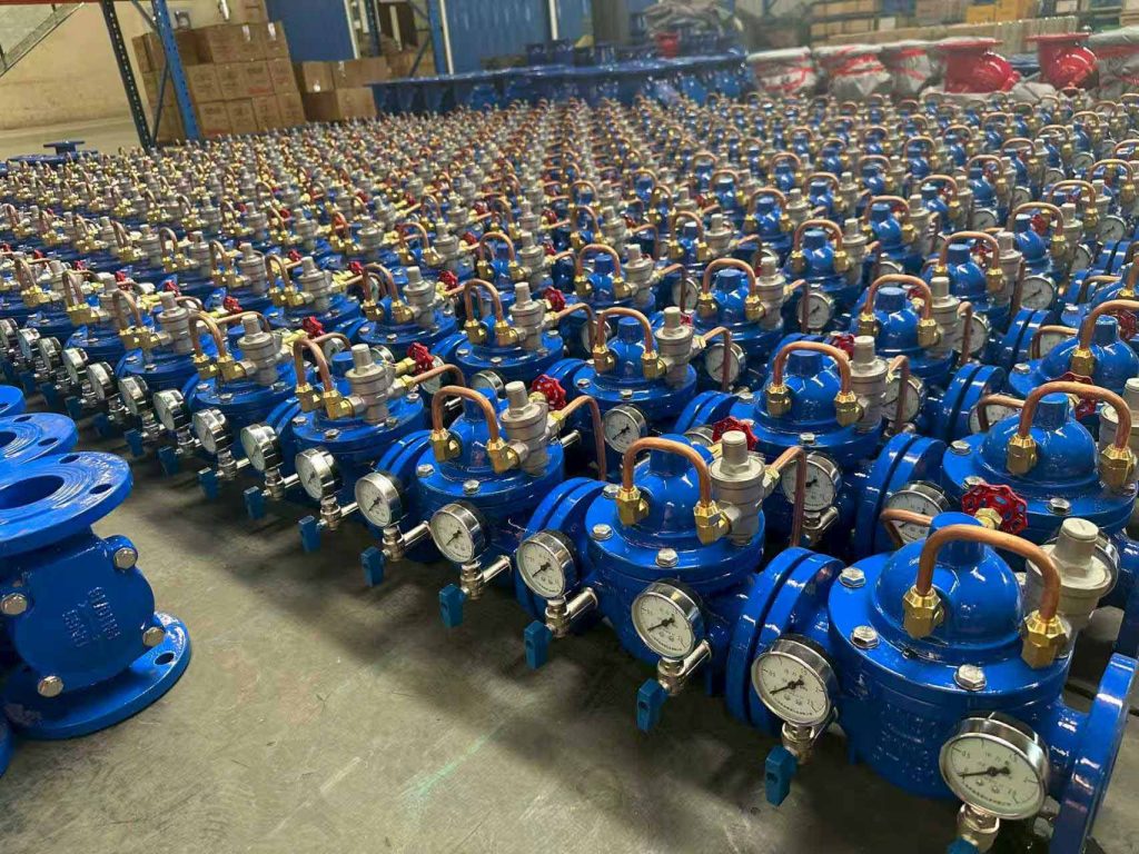
Pressure reducing valves commonly utilized in fire protection systems are primarily categorized into two distinct types: pilot-operated valves and proportional valves.
Pilot-Operated Valves
Pilot-operated valves function based on hydraulic control principles. By modulating the internal throttling area of the valve, they alter the water flow velocity and fluid kinetic energy within the pipeline. This induces a controlled pressure drop in the water flow to achieve the desired pressure reduction and stabilization effects within the network.
During operation, precise regulation ensures a dynamic equilibrium between the pressure fluctuations within the valve body and the opposing spring force. This mechanism enables the valve to maintain the downstream (outlet) pressure stably within a permissible tolerance range. It continuously reduces the high-pressure medium entering the valve to a preset outlet pressure range by harnessing the intrinsic energy of the water flow itself.
Proportional Valves
Conversely, proportional pressure reducing valves employ a pressure reduction mechanism based on a fixed pressure ratio. Common inlet-to-outlet pressure ratios include specifications such as 2:1 or 3:1.
Unlike constant-pressure valves, the downstream pressure of a proportional valve does not remain constant but rather fluctuates synchronously with the upstream (inlet) pressure. When the upstream pressure rises, the downstream pressure increases proportionally, making this type of valve particularly suitable for specific fire protection network scenarios.
Configuration and Installation Requirements for Pressure Reducing Valves
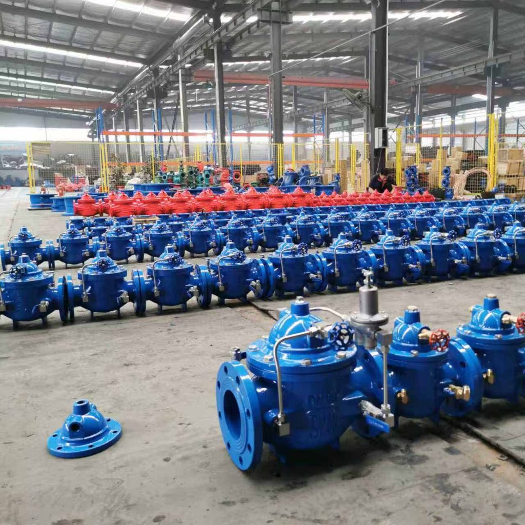
Within fire protection water supply networks, pressure reducing valves must be positioned and installed in strict compliance with engineering standards. For more information on system layouts, you can explore our المنتجات solutions.
Here are the critical installation guidelines:
- Location: Typically, they are situated immediately upstream of the alarm valve assembly. If the system incorporates multiple alarm valve assemblies, a dedicated backup valve must be installed in parallel.
- Filtration: To prevent malfunctions caused by impurities, a strainer must be installed immediately upstream of the inlet. The mesh density should be 4 to 5 meshes per square centimeter, and its effective flow area must be at least four times the cross-sectional area of the pipeline.
- Monitoring: Pressure gauges must be installed both upstream and downstream of the filter and the valve. The gauge dial diameter should be no less than 100 mm.
Flow Direction and Valve Structure
Pressure reducing valves possess an inherent unidirectional flow characteristic, meaning the direction of water flow cannot be reversed. If an adjustable valve is installed in reverse, it will lose its pressure-reducing functionality and serve merely as a check valve.
Control valves must be positioned upstream and downstream to facilitate rapid isolation during maintenance. Furthermore, a pressure test drain valve must be installed on the outlet side, accompanied by a flow detection test port.
When installing proportional valves (which utilize a cylindrical piston-type spool structure), they are most suitable for vertical installation. This ensures the sealing surface of the spool is subjected to uniform force, extending its service life.
Pressure-Reducing Valve Commissioning Requirements
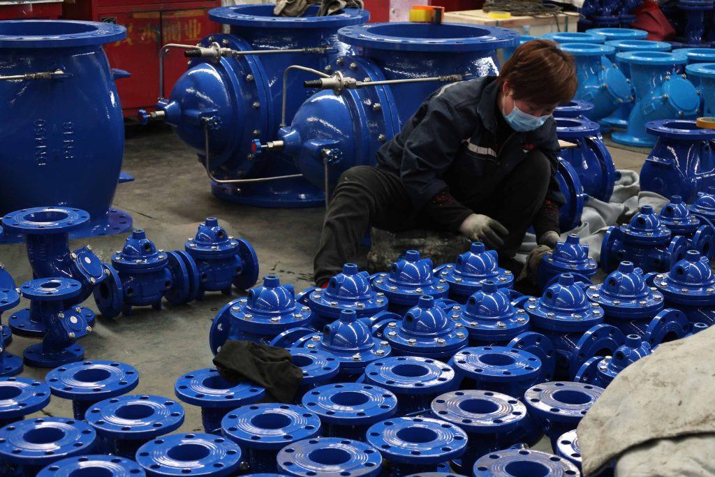
Upon completion of the installation, rigorous system commissioning must be conducted. Both the static and dynamic pressure parameters upstream and downstream of the valve must strictly comply with international safety specifications.
Under test conditions involving flow rates exceeding the nominal rating (specifically 150% of the design flow), the dynamic pressure downstream must not drop below 65% of the nominal design working pressure. Throughout the entire commissioning process, the equipment must not exhibit any significant increase in noise levels across low flow, nominal design flow, and maximum flow scenarios.
Maintenance and Management of Pressure Reducing Valves
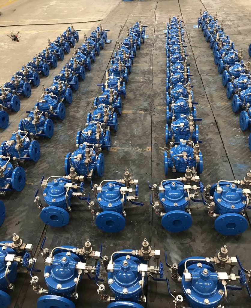
During the routine operation and maintenance phase, a mechanism for periodic inspection is vital for the safety of the water network.
A drainage test should be conducted on the pressure reducing valve assembly on a monthly basis. This must be accompanied by the simultaneous monitoring and recording of pressure readings both upstream and downstream.
Additionally, a comprehensive performance test must be conducted annually. This test should focus primarily on assessing the flow rate and pressure stability, identifying potential equipment hazards, and guaranteeing the valve’s long-term compliance with regulatory standards.
Partner with a Trusted Valve Manufacturer
Ensuring the safety of your water infrastructure starts with high-quality components. At XVS Valve, we specialize in manufacturing and exporting premium ductile iron valves that meet rigorous international standards.
If you are looking for stable pricing, reliable lead times, and expert technical support for your valve procurement, we are ready to partner with you. [Reach out to our team anytime] for a quick quote or technical exchange!